Elektrik

  • Home
  • Privacy Policy
  • About
  • Related

Wednesday, 30 December 2015

Simple 3 Watt and 5 Watt LED Driver Circuit Using IC 338

 dvbot     08:35     12 volt battery led driver for 5 watt and 3 watt, car tail light led driver, led driver for vehicle like motorbike and car, led driver using lm338     1 comment   

The IC LM338 as we probably are aware, is a profoundly adaptable gadget with regards to controlling voltages and current levels.
In the present outline, the gadget is designed in the programmed current control mode.

White LEDs particularly require a very much dimensioned info, actually the current to these LEDs must be entirely controlled.

By interfacing its ADJ pin with the OUTPUT ensures that the current at the OUTPUT is continually checked by the ADJ terminal and is never permitted to go past the foreordained level set by the resistor.

The gadget can bolster no less than 3 amps of current through it, in this manner effortlessly gets to be good to drive 1 to 5 quantities of 1 watt LEDs, each having their own particular current constraining resistors.

The present limiting resistors can be tried different things with, presumably lesser values may be tried for increasing the luminosity levels of the LEDs, however anything under 50 Ohms ought not be attempted, in light of the fact that it may bring about a perpetual harm to the LEDs.

The data to the LM 338 IC can be from a directed DC control supply, fit for supplying 12 volts at 3 amps or more.

The IC LM 338 ought to be mounted over a heatsink for better execution.

The data diode ought to be appraised at 3 amps, so a 1N5408 turns out to be OK for the application.

In the event that the circuit is expected for working outside, the data may be taken from a 12 v battery, as from a vehicles battery.


led driver, 12 volt bike led driver, car led driver
For L = 3 Watt LED:
R = 1.8 Ohms of 2 Watt

For L = 5 Watt LED:
R = 1.05 Ohms of 4 Watt
Read More
  • Share This:  
  •  Facebook
  •  Twitter
  •  Google+
  •  Stumble
  •  Digg

Tuesday, 3 November 2015

Remote control switch on or off for home appliances

 dvbot     11:24     BC548, BC558, Remote control switch on or off for home appliances, using IC CD4017     No comments   

Associate this circuit to any of your home apparatuses (light, fan, radio, and so on) to make the machine turn on/off from a TV, VCD or DVD remote control. The circuit can be activated from up to 10 meters.


The 38kHz infrared (IR) beams produced by the remote control are received by IR collector module TSOP1738 of the circuit.
Pin 1 of TSOP1738 is associated with ground, pin 2 is joined with the power supply through resistor R5 and the output is taken from pin 3. The output signal is increased by transistor T1 (BC558).

The amplifier signal is given to clock pin 14 of decade counter IC CD4017 (IC1). Pin 8 of IC1 is grounded, pin 16 is joined with Vcc and pin 3 is associated with LED1 (red), which shines to demonstrate that the machine is "off."

The output of IC1 is taken from its pin 2. LED2 (green) associated with pin 2 is utilized to demonstrate the "on" condition of the apparatus. Transistor T2 (BC548) joined with pin 2 of IC1 drives hand-off RL1. Diode 1N4007 (D1) goes about as a freewheeling diode. The machine to be controlled is associated between the pole of the relay and neutral terminal of mains. It gets associated with live terminal of AC mains by means of normally opened (N/O) contact when the relay energizes.

remote control your electic appliances like tv computer and fan


Read More
  • Share This:  
  •  Facebook
  •  Twitter
  •  Google+
  •  Stumble
  •  Digg

Simple Car Audio Amplifier Circuit

 dvbot     11:14     amplifier using TDA2003, car amplifier, simple auto amplifier     No comments   

A straightforward low power car stereo amplifier circuit taking into account TDA 2003 is showed here.


The circuit utilizes low cost, promptly accessible components and it is anything but difficult to develop.
TDA2003 is an integrated car radio amplifier from ST Micro electronics that has a ton of good elements like short circuit protection for all the pins, heat over range level low harmonic distortion, low traverse bending and so on.

In the circuit given here each TDA2003 is wired as a mono amplifier working from a 12V DC supply. Resistors R2 and R3 shapes a feedback system that sets the amplifier gain. C7 is the input DC de-coupling capacitor and C5 couples the speaker to the amplifiers yield. C4 is utilized for enhancing the swell dismissal or ripple rejection while C1 and C2 are utilized for power supply filteration. C3 and R1 are utilized for setting the upper frequency cut-off. Network containing C6 and R4 is utilized for frequency adjustment and to avoid oscillation.

audio amplifier, car amplifier, simple amplifier using TDA 2003

Read More
  • Share This:  
  •  Facebook
  •  Twitter
  •  Google+
  •  Stumble
  •  Digg

Friday, 16 October 2015

Using Arduino as a simple Web Server along with Ethernet shield

 dvbot     03:00     arduino mega and uno, arduino web server, atmega328, ethernet shield, simple web server     No comments   

Using an Ethernet shield along with Arduino board you can turn it into a simple web server which can be accessed by anyone on the internet, and by accessing that server with a browser running on any computer connected to the same network as the Arduino board, you can:
  • Control hardware from the webpage like fan or lights (using Javascript buttons).
  • Read the state of a switch which can be either ON or OFF (using simple HTML).
  • Read value of a sensors connected to Arduino board (using simple HTML).


Arduino Board


atmega328 arduino web server http://lifestyle-facts.blogspot.com/


Ethernet Shield


http://elektriktech.blogspot.com/ atmega328 arduino web server http://lifestyle-facts.blogspot.com/

Hardware needed:


To use an Arduino Board as a Simple Web server, you need the following:

   DC Voltage of 5V from Arduino - To power the Ethernet Shield
    Ethernet shield - To connect with LAN
    Connection speed: 10/100Mb - For optimum performance.
    Connection with Arduino on SPI port

The Ethernet shield will connect the Arduino board to the Web or Internet. Setup is very simple, Just plug the header pins of the shield into your Arduino, then connect an Ethernet cable to the shield.  In the figure below, you can see an Arduino Mega with an Ethernet shield installed and connected with internet.

atmega18 arduino web server http://elektriktech.blogspot.com

atmega arduino web server http://elektriktech.blogspot.com

Now let's get to the working.

We will demonstrate how to use the Arduino as a Web server,  in the further experiment we will find how Arduino can show the state of a switch through sending information as a web server. Giving it's output in html pages

Components required:
  • 1 x Ethernet cable
  • 1 x Wi-Fi Router (Optional)
  • 1 x Arduino Mega2560 or Arduino UNO
  • 1 x Ethernet Shield
  • 1 x Breadboard or blank circuit board can do as well
  • 3 x Jumper Wires
  • 1 x 1k Resistor
  • 2 x 9VDC Adaptor
  • 1 x Push button

 Schematic

Wiring Diagram http://elektriktech.blogspot.com

 Connect the components as shown in the figure above. Pin 8 of the Arduino is connected to the Push button. This pin is configured as an INPUT, and when the button is pushed, the Arduino will read a HIGH value on this pin because the current will start flowing in this part. The Arduino will then set the status of the OUTPUT to ON on the webpage it hosts. When it is released, the output will be set to OFF. The status of the switch will available to the Web server as we need it.

Ethernet design

To control the Ethernet shield, you utilize the Ethernet.h library.

The shield must be allocated a MAC and IP address utilizing the Ethernet.begin() function. For a specific gadget, a MAC address is an all around extraordinary identifier. Current Ethernet shields accompany a sticker showing the MAC address. For more seasoned shields, an arbitrary one ought to work, however one should not utilize the same MAC address for many Ethernet Shields. Legitimacy of IP address relies on upon the arrangement of one's network. In the event that DHCP is utilized, it might dynamically assign an IP to the shield.

IP ADDRESS

IP address (Internet Protocol address) is a numerical name allotted to every gadget participating in a PC system that uses the Internet Protocol for correspondence. To indicate the IP address which is done inside the system. It is basic:

byte ip[] = { 192, 168, 0, 112 } and change it to match one own setup. For instance, if the switch's IP location is 192.168.0.60, and the scanner has 192.168.0.40, So I will allot the IP of Ethernet shield to 192.168.0.50 with the assistance of taking after order:

byte ip[] = { 192, 168, 0, 50 };

The initial three bytes ought to be same and it should not have similar IP address as any of other devices connect in same LAN.

MAC ADDRESS

MAC address (media access control location) is an exceptional identifier doled out to every gadget taking an interest in a physical system. Every bit of systems administration gear has an one of a kind serial number to recognize itself over a system and this is typical hard-modified into the hardware's firmware. In any case, with Arduino, we can characterize the MAC address our self.

byte mac[] = { 0x90, 0xA2, 0xDA, 0x0D, 0x85, 0xD9 };

You can set the subnet and portal with the assistance of taking after charges:

byte subnet[] = { 255, 255, 255, 0 }; /allocating subnet veil

byte gateway[] = { 192, 168, 0, 1 }; /allocating entryway

Along these lines, to setup Ethernet Shield, the square of code is given below:

/********************ETHERNET SETTINGS ********************/

byte mac[] = { 0x90, 0xA2, 0xDA, 0x0D, 0x85, 0xD9 }; /allotting MAC address

byte ip[] = { 192, 168, 0, 112 }; /ip in lan

byte subnet[] = { 255, 255, 255, 0 }; /allotting subnet mask

byte gateway[] = { 192, 168, 0, 1 }; /allotting default gateway

The following is a picture of the connection, demonstrating how the Arduino board unites with the Wi-Fi switch. The Ethernet link associate shield with the switch and switch then join remotely with the portable workstation. Or you can just connect the Ethernet shield directly to your home router or switch.

http://elektriktech.blogspot.com

Program
Below is the script that outputs HTML of a simple Web page.

client.println("<!DOCTYPE html>"); //web page is made using HTML

client.println("<html>");

client.println("<head>");

client.println("<title>Ethernet Tutorial</title>");

client.println("<meta http-equiv=\"refresh\" content=\"1\">");

client.println("</head>");

client.println("<body>");

client.println("<h1>A Webserver Tutorial </h1>");

client.println("<h2>Observing State Of Switch</h2>");

client.print("<h2>Switch is: </2>");

if (digitalRead(8))

{

client.println("<h3>ON</h3>");

}

else

{

client.println("<h3>OFF</h3>");

}


client.println("</body>");

client.println("</html>");

This program will display a web page on a Web browser when the IP address assigned to the Arduino is accessed.
The line:

client.println("<http-equiv=\"refresh\" content=\"1\">");

Educates the browser to refresh the page. At the point when the page is accessed once again, the Arduino will again read the switch's status and present it in the output.
Recall that, you can simply see the source code of the displayed Web page. On pushing the push button, you can watch the changing condition of the switch in the webpage.
You can likewise set this up to keep running without the switch. To do this you have to:
  1. Assign a manual IP address to the Arduino's Ethernet say 192.168.0.2 and Subnet mask 255.255.255.0 default Gateway empty.
  2. Use a cross-over Ethernet cable to link the two (laptop and Arduino).
  3. We should then be able to get your Arduino site up on http://192.168.0.2 from the laptop.
Below is the code that you would load into the Arduino to connect it directly to the PC without the router:


#include <SPI.h>
#include <Ethernet.h>


/******************** ETHERNET SETTINGS ********************/

byte mac[] = { 0x90, 0xA2, 0xDA, 0x0D, 0x85, 0xD9 }; //physical mac address
byte ip[] = { 192, 168, 0, 112 }; // ip in lan
byte subnet[] = { 255, 255, 255, 0 }; //subnet mask
byte gateway[] = { 192, 168, 0, 1 }; // default gateway
EthernetServer server(80); //server port


void setup()
{
Ethernet.begin(mac,ip,gateway,subnet); // initialize Ethernet device
server.begin(); // start to listen for clients
pinMode(8, INPUT); // input pin for switch
}

void loop()
{
EthernetClient client = server.available(); // look for the client

// send a standard http response header

client.println("HTTP/1.1 200 OK");
client.println("Content-Type: text/html");
client.println("Connnection: close");
client.println();

/*
This portion is the webpage which will be
sent to client web browser one can use html , javascript
and another web markup language to make particular layout
*/


client.println("<!DOCTYPE html>"); //web page is made using html
client.println("<html>");
client.println("<head>");
client.println("<title>Ethernet Tutorial</title>");
client.println("<meta http-equiv=\"refresh\" content=\"1\">");

/*
The above line is used to refresh the page in every 1 second
This will be sent to the browser as the following HTML code:
<meta http-equiv="refresh" content="1">
content = 1 sec i.e assign time for refresh
*/


client.println("</head>");
client.println("<body>");
client.println("<h1>A Webserver Tutorial </h1>");
client.println("<h2>Observing State Of Switch</h2>");

client.print("<h2>Switch is: </2>");

if (digitalRead(8))
{
client.println("<h3>ON</h3>");
}
else
{
client.println("<h3>OFF</h3>");
}

client.println("</body>");
client.println("</html>");

delay(1); // giving time to receive the data

/*
The following line is important because it will stop the client
and look for the new connection in the next iteration i.e
EthernetClient client = server.available();
*/

client.stop();

} 
 
Hope you liked this project. For more projects related to Arduino or any other electronic please message me or write them in the comments. 
Read More
  • Share This:  
  •  Facebook
  •  Twitter
  •  Google+
  •  Stumble
  •  Digg

Thursday, 8 October 2015

Simple +-400Watt Amplifier using TDA7294 or TDA7293 + Power Transistors 2SC5200 and 2SA1943

 dvbot     00:47     powerful amplifier using tda7293 and tda7294 using extra transistors 2sc5200 and 2sa1943, transistor and chip amp hybrid     No comments   

This additional part can be added to the traditional chip amp made using TDA7294 or TDA7293 to gain extra power in output.
The traditional chip amp produces about 40-50watt rms output which isn't any less but by adding these power transistors it can maximize the output to extreme.

This is the classic TDA7294 AMP with LOTS more Power then normal, this is with using Power Transistors at the output stage, it is a simple Addon to make, it just requires a SYNC resistor and the feedback to be moved to the output after the Power Transistors.

So to make this AMP you can just start with the TDA7294 with one change, just need to "move" the feedback so you can connect it to the Output after the Power Transistors, in all the AMPS that have been made with the TDA7294 the 6.8Ohm has been spot on when using the 2SC5200 & 2SA1943, if you use other transistors you may need to experiment with another value for the SYNC resistor.

Things to do when SYNC it is to listen to it, things to listen to are from very low volume (FROM a clean source) and go slowely up in volume, the POINT here is that it should just get louder like a normal amplifier would, if the SYNC is off then a normal thing will be that at audio peaks (like drums & bass) it will sound like someone is kicking your speakers because the Transistors kick in at a wrong volume then the amp is playing, believe me you will hear it, this needs to be corrected by changing the resistor else you will have an amp that only sounds good at very low volume and medium to high volume.


Component list: (1x AMP)
1x 680 (680R) Resistor
1x 10K Resistor
3x 22K Resistor
1x 6.8 (6R8) 5W Resistor
2x 0.15 (0R15) 5W Resistor
2x 10uF 50V Capacitor
2x 22uF 50V Capacitor
1x 1uF 63V MKT/BiPolar Capacitor
1x TDA7294 Chip AMP
1x 2SA1943 PNP Transistor
1x 2SC5200 NPN Transistor


http://elektriktech.blogspot.com/ amplifier using tda7293 and tda7294


Output Power: The output is at 400W+ (MAX) and this is based on that the TDA itself adds ONLY 20-40W (because of the much higher driving Ohm), but the 5200/1943 are some GOOD POWERFULL transistors and going through the datasheet it will deliver peeks over 600W (short pulse pr Transistor), they supply 100W but this is FULL DC and there are no audio tracks to my knowledge that has that kind of "sound"
Driving Impedance: We have been using it for 2-8Ohm speakers, the lowest we have driven was 1.3Ohm but as with all AMPS if you know your Transistors you know how many watts you can pull out, this AMP will drive what ever you hook it up to, JUST one thing, when we were using my 1.3Ohm set it did introduce some "noise" (sounded like 80' AMP hiss), and at this point the SYNC resistor properly needs to be changed, we did not do this, we took the lazy way out and put some 1.8Ohm POWER Resistors in line with the speakers instead.

We have been using this AMP for +3 years, it is good for driving 2-8Ohm speakers with current config (6.8Ohm RES & 5200/1943)
Read More
  • Share This:  
  •  Facebook
  •  Twitter
  •  Google+
  •  Stumble
  •  Digg

Tuesday, 29 September 2015

Stun Gun Circuit Diagram using 555 timer IC

 dvbot     12:30     bd679 stun gun, stun gun using 555 timer ic, timer ic 555     No comments   

CAUTION: Before going to explain about this circuit, we are going to strictly suggest that DO NOT TRY TO IMPLEMENT IT PRACTICALLY AS IT PRODUCES VERY HIGH VOLTAGE. 
DO IT ONLY UNDER A PROFESSIONAL'S GUIDANCE!


A stun gun is usually a device used to produce a very high voltage, low current signal and is used mostly as a weapon to stun or send shock waves to the target with the intention to weaken or paralyze the target.


However moving towards to design the circuit, it should be kept in mind that in some countries, stun gun is banned so this project is only for educational purpose. 
Because, this is actually a lethal weapon which can render a person mentally and physically paralyzed. It is usually powered by a 12 Volt battery or by a 12Volt DC adapter. 
The stun gun circuit uses a 555 Timer to produce a current fluctuating signal and a voltage multiplier using a transformer and a multiple stage (8) arrangement of voltage doublers using capacitors and diodes.


STUN GUN - http://elektriktech.blogspot.com


You can use a Mosfet in place of BD679. For eg: IRF220

 As soon as the switch is pressed, the operation of 555 Timer starts. A pulsating electric signal of low current is produced because of supply, which is stepped up using a step up transformer, to a voltage of around 1000V. The signal from the Timer is fed through the transistor switch.

All this results in the output of around a thousand volt which is enough to stun the target for some minutes.
Read More
  • Share This:  
  •  Facebook
  •  Twitter
  •  Google+
  •  Stumble
  •  Digg

A simple 12V battery charger schematic using LM317

 dvbot     04:16     12 volt dc battery charger using lm317 with output display, battery charger, lm317 ic     2 comments   

This is a simple 12Volt Battery Charger Circuit which can be made using less components.

This circuit can be modified using the formulas given on it. Using the formulas the components can be changed to work with your battery.

12 volt dc battery charger http://elektriktech.blogspot.com


It provides a fuse, as the positive and negative charge reversal protection, output short circuit protection, also protects if the output voltage exceeds 2V, it can also limit the current output.

An Ampere Meter can be used in series with the battery to check the output current to battery. Usually the output current should be below 10-15 Ampere.

Read More
  • Share This:  
  •  Facebook
  •  Twitter
  •  Google+
  •  Stumble
  •  Digg

Wednesday, 19 August 2015

500 Watt Inverter using Transistor 2N3055 along with Transformer ratings

 dvbot     04:11     500w inverter circuit, 500watt inverter, corrected circuit, inverter circuit, inverter using 2n3055     No comments   

This Circuit has been corrected while it had minor issues in the past, the circuit has been fully debugged for any problems and made 100% working now.


Utilizing this circuit you can change over the 12V DC into the 220V AC. In this circuit 4047 is utilized to create the square wave of 50hz and increase the current and afterward amplify the voltage by utilizing the step up transformer.

inverter using 2n3055 - http://elektriktech.blogspot.com 

 To calculate the Transformer rating for this circuit:

The basic formula is P=VI and between input output of the transformer you have 
Power input = Power output

For example if you want a 220W output at 220V then we need 1A at the output. Then at the input you must have at least 18.3V at 12V because: 12V*18.3 = 220v*1

So you have to wind the step up transformer 12v to 220v but input winding must be capable to handle strong power of 20A.
Read More
  • Share This:  
  •  Facebook
  •  Twitter
  •  Google+
  •  Stumble
  •  Digg

Monday, 10 August 2015

Making your own 10,000 to 25,000 volt capacitor

 dvbot     14:05     10k free energy, 10k to 25k volt capacitor, capacitor, caps, diy, diy capacitor, free power source, HV capacitors, hv caps, make your own capacitor, Making your own 10k capacitor     No comments   

We are going to make a big High Voltage Capacitor, so please do not try this unless you are an expert in handling high voltage equipments.


hv capacitor - http://elektriktech.blogspot.comhv capacitor - http://elektriktech.blogspot.com 
 In our above HV Capacitor design, we used a clear plastic make up container that we purchased from a local market.  We then purchased 5” x 50 foot aluminum sheeting from a hardware store, you will need 2 rolls.  We then cut the aluminum in small pieces of 5” x 6” sheets. Once you are done with cutting both rolls up. Then you will need to make your bolt holes on the ends of your positive and your negative plates. You will need a good 3-M spray adhesive, which must spray a fine spray, you can Purchase this at any Hardware or Art Store. Now you will need to cut 6” x 6” plastic Mylar pieces for your die electric.
 You will need to bond them to the aluminum plates. Use a 3 mill or a 4 mill plastic, this should hold up under 10,000 vdc. 
Cut a small piece of ½”plywood to 5” x 6” then drill your bolt holes using the + and negative plate as a template, Now you will need a small drill press, set up a wood jig with register marks so you can drill holes in all the other aluminum plates in the exact same spot. Holes should be a little bigger than
the bolt. Even out 2 stacks of 5” x 6” aluminum plates, start off drilling the one stake first and mark each one as +.
 This will help you later and you will thank me for it. Then do the Neg plates the same way. Make sure you drill holes in the exact same place, so all bolt holes will line up correctly when you push the holding bolts through. When you are finished drilling holes, place 4 guide bolts through the bottom of your plywood base. Using these bolts as guides.
hv capacitor free energy - http://elektriktech.blogspot.comNow spray the top of the plywood with adhesive. Now place your first 5” x 6” + plate on it, press down firmly. Now spray your mylar plastic on a sheet of cardboard away from your project, spraying only one side, you want to keep the spray away from your project or it will build up on your bolts. Now place the mylar to the right side of the holes, press firmly, now spray one side of your Neg. Plate and insert over the right side bolts. The left bolts are for your + plates and the Right side is for your Negative plates. Now repeat this over and over again.
Be careful and not to forget to place Mylar plastic in-between each + and Negative plate. Or they will short out.
It will take you about 16 hrs of work to finish, once you are done place 2 bolts on the top of your plastic lid. Connect the left one to the left bolts using 8 gauge wire or wire rated for the amount of voltage and amperage you are going to use capacitor for, do the same for the right.


Read More
  • Share This:  
  •  Facebook
  •  Twitter
  •  Google+
  •  Stumble
  •  Digg

Saturday, 8 August 2015

Doing a Country Style track lighting.

 dvbot     13:58     country style, LED, led track lighting, modern lighting, track, track lighting     No comments   

Track lighting is another expansion in enriching our homes environment. It gives an extremely lovely lightning effect. One can change its brightening through a control unit in regards to the amount of light is needed. 

They can be introduced in the kitchens and most perfect spot would be the lounge and rooms relying on their shape and the way of the client or occupant. These lights can be set near the windows, flower pots, book retires, and chimneys. 


led track lighting - lifestyle-facts.blogspot.com


Track lights don't give brilliant light, yet the general impact is simply enhancing and gives a mood to the room. Specially framed and different shaped lights are accessible for the billiard table, kitchen table and some even molded as country utensils and western legacy ornamental styles. It is most suitable to utilize them where the roof tallness is adequate and the pendant can hand freely. These are found in distinctive shades, for example, nickel, bronze, metal, dark, chestnut, gold, copper, chrome, rust, silver and so on. 
led track lighting - lifestyle-facts.blogspot.com

Arrangement should be possible in any structure, as a group forming a triangle, or inline or circle.

These lights must be mounted with the minimum height of 24 to 30 inches over the floor. On the off chance that more than two lights are utilized, customizable bars can be used.

Pure typical country track lights are the, cart wheel, milk jug in copper and brass, spur, lantern, chime, clock and numerous others. Each style likewise speaks to the culture of the district and acts and bringing close the people. They deliver the impact of warmth and convenience which other bright lights and modern lights don't. The costs range from 50 US$ to some even 1000 US$. Organizations into business are additionally offering altered style too. 


led track lighting - lifestyle-facts.blogspot.com


Other suitable spots for these lights are on top of the windows, flower pots, fish aquarium, and corners of the dinning room, sitting lounge or family room. You can put them on entryways, stair lobbies where they can be utilized as a part of a solitary line. Lights fit as a fiddle of bell, or cart wheel, or lantern give a delicate look when utilized as a part of the dinning region making the room in all more pleasing and inviting. 


Installation
If you already acquire a ceiling light fixture, track lights are anything but difficult to introduce. Basically remove the old apparatus, screw the track into the roof utilizing toggle botls or other fitting grapples, connect the new track to the electrical box, snap your lights set up and appreciate the enjoyment of moving them around to get the lighting in your room precisely the way you need it!


led track lighting - lifestyle-facts.blogspot.com

You can discover boundless approaches to put the track lights in and around your home. The idea is basically to give light and improve style and magnificence of your home with a low power bill. With LED track lighting framework you can make sure of sparing a considerable measure on your energy cost as these don't consume much power.
Read More
  • Share This:  
  •  Facebook
  •  Twitter
  •  Google+
  •  Stumble
  •  Digg

Monday, 3 August 2015

While innovation is at it's peak are you still wondering how solar panels work?

 dvbot     04:00     how do solar panels work, photovoltaic, renewable energy, solar energy, solar panels     No comments   

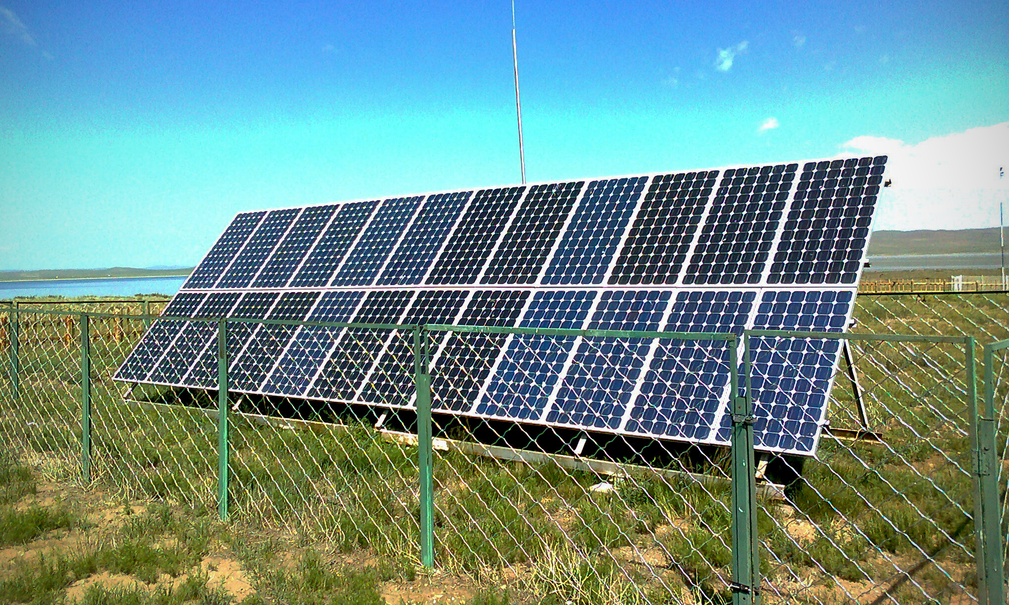
Solar Panels are turning out to be more well known today as a distinct option for conventional power era systems. By utilizing Solar Panels, we can outfit the Heat and Light energy gave by the sun and create power for anything from an icebox to a car. Have you ever seen Solar Panel secured rooftops or school zone signs with Solar Panels on and thought about how these Solar Panels work and what's going ahead "behind the boards?" "How do solar panels work?"


Lets take a gander at what Solar Panels are involved of and how solar panel innovation functions.

how do solar panels work - http://lifestyle-facts.blogspot.com


Solar Panel innovation is taking into account 2 sorts of sunlight based warmth accumulation: Solar power collectors and solar cells. Since for all intents and purposes of making solar cells are based on Solar panels, we'll concentrate on the Solar panel innovation. Solar cells, otherwise called photovoltaic cells, is the thing that makes up a photovoltaic board, or all the more regularly known as a Solar Panel. Try not to let the word photovoltaic threaten you. Lets break the word separately: photograph = light and voltaic = power (consider volt or voltage).

how do solar panels work - http://lifestyle-facts.blogspot.com


Basically it's speaking to the thought of changing over light into power. These photovoltaic cells are basically embody a semi-conductor, most generally silicon. I'm certain you have found out about silicon, and are really utilizing the innovation at this moment... in your Personal Computer, Silicon is utilized as a part of microchips, is is also utilized in every electronic semiconductor around the globe, is an exceptionally well known semi-conduit. At the point when light hits these silicon filled PV cells, the sunlight based vitality is consumed and a current is delivered inside the cell. By hanging together these Photovoltaic cells into a Solar panels, and putting contacts on the outside of this board, we have the capacity to take advantage of this electrical current.

how do solar panels work - http://lifestyle-facts.blogspot.com


Now that you know how Solar Panels work, what happens next?

When we have the Solar Panels wired and cooperating, they should be deliberately put in request to ensure they are presented to most extreme daylight. On account of utilizing solar panels at home, the rooftop would be the perfect place for the Solar Panels. It is essential to give careful consideration to the edge and situation of the boards to guarantee that Solar Panels work at their most elevated effectiveness. On the off chance that even one of the sun based cells is not completely presented to daylight, it can incredibly decrease the effectiveness of the whole board. It is likewise truly basic to change the edge of the boards through out the year so as to keep the solar panels presented to daylight amid the distinctive seasons. This may or may not be vital for you relying upon your individual design.

Right now we have created power, however the procedure is not complete yet. So as to have the capacity to utilize this vitality inside your home, we have to first change over the current from an Direct Current (DC) to an Alternate current (AC). To do this, we can utilize an inverter, which changes over this power into an AC current that family machines utilize. For example, an icebox or ventilation system have the capacity to utilize AC voltage. Another great step is to verify you store this vitality for times when either there is practically no daylight, for example, during the evening. This should be possible by putting away this power in batteries.


how do solar panels work - http://lifestyle-facts.blogspot.com

Deep cycling Batteries permit you to completely charge and revive using the current obtained from Solar Panels, keeping in mind the end goal to draw small amount of current over quite a long time. This is completely different from a car battery, where you require a bigger power boost for a brief time, i.e. when you ignite your car.

how do solar panels work - http://lifestyle-facts.blogspot.com


Next time you see Solar Panels at work, you'll see that it is a combination of Solar cells. On the off chance that you look carefully enough, you can see the individual Photovoltaic cells that make up each solar panels. Additionally, observe the boards position. Hope to perceive how others have expanded the boards presentation to the sun, by the stature, point, and situation of the board keeping in mind the end goal to permit the Solar Panels to work most productively.
Read More
  • Share This:  
  •  Facebook
  •  Twitter
  •  Google+
  •  Stumble
  •  Digg

Friday, 31 July 2015

Audio Clipping Peak Indicator using IC TL062

 dvbot     11:25     amplifier level indicator, ic TL062, peak level indicator, simple peak level     No comments   

This Simple Audio Clipping Peak Indicator circuit was expected to distinguish clipping in preamp stages, mixers, equalizer, amplifiers and so on. It can be utilized as a different, convenient unit, to signal by using some LEDs when the output wave form a specific sound stage is "cutting" i.e. is coming to the onset of its maximum permitted peak voltage value before an over-load is happening. This will help the operator in avoiding extreme twisting or distortion in the audio to be created through the sound hardware chain, as if it were shielding your amplifier equipments and speakers from over-loading.


This unit is particularly useful in signaling overload of the input stages in mixers, PA or musical instruments amplification chains, but is also suited to power amplifiers. A careful setting of Trimmer R5 will allow triggering of the LED with a wide range of peak-to-peak input voltages, in order to suit different requirements.

Unfortunately, an oscilloscope and a sine wave frequency generator are required to accurately setup this circuit. Obviously, the unit can be embedded into an existing mixer, preamp or power amplifier, and powered by the internal supply rails in the 9 – 30V range. The power supply can also be obtained from higher voltage rails provided suitable R/C cells are inserted. SW1 and B1 must obviously be omitted.

Circuit Operation
The heart of the audio clipping circuit is a window comparator formed by two op-amps packaged into IC1. This technique allows to detect precisely and symmetrically either the positive or negative peak value reached by the monitored signal. The op-amps outputs are mixed by D1 and D2, smoothed by C4, R7 and R8, and feed the LED driver Q1 with a positive pulse. C5 adds a small output delay in order to allow detection of very short peaks.

audio clipping peak indication using ic TL062 lifestyle-facts.blogspot.com

Notes:
  • With the values shown, the circuit can be easily set up to detect sine wave clipping from less than 1V to 30V peak-to-peak (i.e. 15W into 8 Ohms). If you need to detect higher output peak-to-peak voltages, R1 value must be raised. On the contrary, if the circuit will be used to detect only very low peak-to-peak voltages, it is convenient to lower R1 value to, say, 220K omitting C2. In this way, the adjustment of R5 will be made easier.
  • Using a TL062 chip at 9V supply, stand-by current drawing is about 1.5mA and less than 10mA when the LED illuminates. With TL072 or TL082 chips, current drawing is about 4.5mA and 13mA respectively.
  • When using power supplies higher than 12V, the value of R10 must be raised accordingly.
  • When using power supplies higher than 25V, the working voltage value of C5 must be raised to 35 or 50V.
Parts
R1 – 1M 1/4W Resistor (See Notes)
R2,R3,R8 – 100K 1/4W Resistors
R4,R6 – 10K 1/4W Resistors
R5 – 5K 1/2W Trimmer Cermet or Carbon
R7 – 2K2 1/4W Resistor
R9 – 22K 1/4W Resistor
R10 – 1K 1/4W Resistor (See Notes)
C1,C4 – 220nF 63V Polyester Capacitors
C2 – 4p7 63V Ceramic Capacitor (See Notes)
C3 – 220µF 25V Electrolytic Capacitor
C5 – 10µF 25V Electrolytic Capacitor (See Notes)
D1,D2 – N4148 75V 150mA Diodes
D3 – LED (Any dimension, shape and color)
Q1 – BC547 45V 100mA NPN Transistor
IC1 – TL062 Dual Low current BIFET Op-Amp (or TL072, TL082)
SW1 – SPST Toggle or Slide Switch or Any other switch
B1 – 9V PP3 Battery or a 9V DC power source. Should read at least 1 Ampere.
Read More
  • Share This:  
  •  Facebook
  •  Twitter
  •  Google+
  •  Stumble
  •  Digg

Friday, 24 July 2015

How to make a 2 Watt audio amplifier from discrete components

 dvbot     07:25     2N3906, 3 watt amplifier, BD139, BD140, simple     No comments   

A 2 Watt audio amplifier made from discrete components.


A simple 2 Watt RMS Audio Amplifier which can be made from limited components.

2 watt rms audio amplifier 

Notes
This was one of the earliest circuits that I ever designed and built, in Spring 1982. At that time I had only an analogue meter and a calculator to work with. Although not perfect, this amplifier does have a wide frequency response, low harmonic distortion about 3%, and is capable of driving an 8 ohm speaker to output levels of around 5 watts with slightly higher distortion. Any power supply in the range 12 to 18 Volts DC may be used.

Circuit
The amplifier operates in Class AB mode; the single 470R preset resistor, PR1 controls the quiescent current flowing through the BD139/140 complimentary output transistors. Adjustment here, is a trade-off between low distortion and low quiescent current. Typically, under quiescent conditions, current is about 15 mA rising to 150 mA with a 50 mV input signal. The frequency response is shown below and is flat from 20Hz to 100kHz:

Bode Plot
2 watt audio amplifier 

 The circuit is DC biased so that the emitters of the BD139 and BD140 are at approximately half supply voltage, to allow for a maximum output voltage swing. R9 and R10 provide a degree of temperature stabilization which works as follows. If the output transistors are warm, the emitter currents will increase. This causes a greater voltage drop across R9 and R10 reducing the available bias current. All four transistors are direct coupled which ensures:-

(i) A good low frequency response
(ii) Temperature and bias change stability.

DC Voltages of Prototype
The following voltage checks were made on my prototype. All voltage are made with respect to (wrt) 0 Volt and shown in the table below.

The BC109C and 2N3906 operate in common emitter. This alone will provide a very high open loop gain. The output BD139/140 pair operate in emitter follower, allowing the amplifier to drive low impedance speakers. The signal to noise ration is shown below:


Signal to Noise Ratio:
2 watt audio amplifier


This amplifier has a S/n ratio of 115dB at 1kHz. Overall gain is provided by the ratio of the 22k and 1k resistor. A heat sink on the BD139/140 pair is recommended but not essential, though the transistors will run "hot" to the touch.

Fourier Analysis
A quick measure of the distortion of this amplifier was performed. Operating on a 15V DC power supply with an input sinusoidal waveform of 100mV peak to peak at 1KHz produced the following results in Tina.

Fourier Coefficients
2 watt audio amplifier


The number of samples was set to 4096 and Fourier coefficients up to the 16th harmonic were calculated. The sum of the all harmonics up to 16KHz amounted to just under 2.9% total harmonic distortion, the results are plotted below.

Harmonic Distortion
2 watt audio amplifier


The second and third harmonic are the biggest contribution to overall distortion. Choosing a different amplifier design, a different visaing scheme or more evenly match components can reduce distortion accordingly. At the time this amplifier was made, I only had an analogue multimeter, so all things considered, it was not too bad an effort.

Picture of my Prototype
Finally an image of the original which has stood the test of time. The BD139,140 power transistors can be seen on the left hand side, the preset near top center, the BC109C center right and 2N3906 is buried under a miniature screened audio cable, center bottom.


2 watt audio amplifier


Tenergy Rechargeable LiFePO4 12V 7Ah 89.6Wh Battery
Cheap 12V Battery for the project above
Read More
  • Share This:  
  •  Facebook
  •  Twitter
  •  Google+
  •  Stumble
  •  Digg
Newer Posts Older Posts Home

Popular Posts

  • Simple +-400Watt Amplifier using TDA7294 or TDA7293 + Power Transistors 2SC5200 and 2SA1943
    This additional part can be added to the traditional chip amp made using TDA7294 or TDA7293 to gain extra power in output. The traditional c...
  • Audio Amplifier - 2N3055 MJ2955
    Here is A amplifier with 2n3055 transistors on its output for those of you that are looking at doing a bang for buck amplifier with all tho...
  • Stun Gun Circuit Diagram using 555 timer IC
    CAUTION: Before going to explain about this circuit, we are going to strictly suggest that DO NOT TRY TO IMPLEMENT IT PRACTICALLY AS IT PR...
  • Simple 3 Watt and 5 Watt LED Driver Circuit Using IC 338
    The IC LM338 as we probably are aware, is a profoundly adaptable gadget with regards to controlling voltages and current levels. In the pres...
  • A simple 12V battery charger schematic using LM317
    This is a simple 12Volt Battery Charger Circuit which can be made using less components. This circuit can be modified using the formulas giv...
  • Simple 150 Watt amplifier circuit using transistors
    This is the cheapest 150 Watt amplifier circuit you can make,I think.Based on two Darlington power transistors TIP 142 and TIP 147 ,this c...
  • How to easily repair Momentary Switches used in boats
    Momentary switches make generators and motors begin at the push of a catch. In any case, when they don't begin, consider the switch as o...
  • All the new content will be added to new blog - http://elektriktech.blogspot.com/
    Please visit the new blog http://elektriktech.blogspot.com/ for new content. Apologies for the inconvenience.     http://elektrikte...
  • Simple Car Audio Amplifier Circuit
    A straightforward low power car stereo amplifier circuit taking into account TDA 2003 is showed here. The circuit utilizes low cost, promptl...
  • Lead Acid Battery Charger Circuit
    To successfully charge a battery, it should be supplied with DC current and not AC. This circuit shows how you can use DC voltage to regulat...

Pages

  • Home

Blog Archive

  • ►  2016 (2)
    • ►  August (2)
  • ▼  2015 (23)
    • ▼  December (1)
      • Simple 3 Watt and 5 Watt LED Driver Circuit Using ...
    • ►  November (2)
      • Remote control switch on or off for home appliances
      • Simple Car Audio Amplifier Circuit
    • ►  October (2)
      • Using Arduino as a simple Web Server along with Et...
      • Simple +-400Watt Amplifier using TDA7294 or TDA729...
    • ►  September (2)
      • Stun Gun Circuit Diagram using 555 timer IC
      • A simple 12V battery charger schematic using LM317
    • ►  August (4)
      • 500 Watt Inverter using Transistor 2N3055 along wi...
      • Making your own 10,000 to 25,000 volt capacitor
      • Doing a Country Style track lighting.
      • While innovation is at it's peak are you still won...
    • ►  July (10)
      • Audio Clipping Peak Indicator using IC TL062
      • How to make a 2 Watt audio amplifier from discrete...
    • ►  June (2)
  • ►  2013 (1)
    • ►  July (1)
  • ►  2011 (3)
    • ►  August (3)

Dear Visitor

Please visit the new blog http://elektriktech.blogspot.com/ for latest and updated content.

Contact Form

Name

Email *

Message *

About Me

dvbot
View my complete profile

UPDATE!

Please visit the new blog http://elektriktech.blogspot.com/ for all new contents.

Translate

Subscribe To

Posts
Atom
Posts
All Comments
Atom
All Comments

Copyright © Elektrik
Distributed By My Blogger Themes | Blogger Theme By NewBloggerThemes