Elektrik

  • Home
  • Privacy Policy
  • About
  • Related

Thursday, 8 October 2015

Simple +-400Watt Amplifier using TDA7294 or TDA7293 + Power Transistors 2SC5200 and 2SA1943

 dvbot     00:47     powerful amplifier using tda7293 and tda7294 using extra transistors 2sc5200 and 2sa1943, transistor and chip amp hybrid     No comments   

This additional part can be added to the traditional chip amp made using TDA7294 or TDA7293 to gain extra power in output.
The traditional chip amp produces about 40-50watt rms output which isn't any less but by adding these power transistors it can maximize the output to extreme.

This is the classic TDA7294 AMP with LOTS more Power then normal, this is with using Power Transistors at the output stage, it is a simple Addon to make, it just requires a SYNC resistor and the feedback to be moved to the output after the Power Transistors.

So to make this AMP you can just start with the TDA7294 with one change, just need to "move" the feedback so you can connect it to the Output after the Power Transistors, in all the AMPS that have been made with the TDA7294 the 6.8Ohm has been spot on when using the 2SC5200 & 2SA1943, if you use other transistors you may need to experiment with another value for the SYNC resistor.

Things to do when SYNC it is to listen to it, things to listen to are from very low volume (FROM a clean source) and go slowely up in volume, the POINT here is that it should just get louder like a normal amplifier would, if the SYNC is off then a normal thing will be that at audio peaks (like drums & bass) it will sound like someone is kicking your speakers because the Transistors kick in at a wrong volume then the amp is playing, believe me you will hear it, this needs to be corrected by changing the resistor else you will have an amp that only sounds good at very low volume and medium to high volume.


Component list: (1x AMP)
1x 680 (680R) Resistor
1x 10K Resistor
3x 22K Resistor
1x 6.8 (6R8) 5W Resistor
2x 0.15 (0R15) 5W Resistor
2x 10uF 50V Capacitor
2x 22uF 50V Capacitor
1x 1uF 63V MKT/BiPolar Capacitor
1x TDA7294 Chip AMP
1x 2SA1943 PNP Transistor
1x 2SC5200 NPN Transistor


http://elektriktech.blogspot.com/ amplifier using tda7293 and tda7294


Output Power: The output is at 400W+ (MAX) and this is based on that the TDA itself adds ONLY 20-40W (because of the much higher driving Ohm), but the 5200/1943 are some GOOD POWERFULL transistors and going through the datasheet it will deliver peeks over 600W (short pulse pr Transistor), they supply 100W but this is FULL DC and there are no audio tracks to my knowledge that has that kind of "sound"
Driving Impedance: We have been using it for 2-8Ohm speakers, the lowest we have driven was 1.3Ohm but as with all AMPS if you know your Transistors you know how many watts you can pull out, this AMP will drive what ever you hook it up to, JUST one thing, when we were using my 1.3Ohm set it did introduce some "noise" (sounded like 80' AMP hiss), and at this point the SYNC resistor properly needs to be changed, we did not do this, we took the lazy way out and put some 1.8Ohm POWER Resistors in line with the speakers instead.

We have been using this AMP for +3 years, it is good for driving 2-8Ohm speakers with current config (6.8Ohm RES & 5200/1943)
Read More
  • Share This:  
  •  Facebook
  •  Twitter
  •  Google+
  •  Stumble
  •  Digg

Tuesday, 29 September 2015

Stun Gun Circuit Diagram using 555 timer IC

 dvbot     12:30     bd679 stun gun, stun gun using 555 timer ic, timer ic 555     No comments   

CAUTION: Before going to explain about this circuit, we are going to strictly suggest that DO NOT TRY TO IMPLEMENT IT PRACTICALLY AS IT PRODUCES VERY HIGH VOLTAGE. 
DO IT ONLY UNDER A PROFESSIONAL'S GUIDANCE!


A stun gun is usually a device used to produce a very high voltage, low current signal and is used mostly as a weapon to stun or send shock waves to the target with the intention to weaken or paralyze the target.


However moving towards to design the circuit, it should be kept in mind that in some countries, stun gun is banned so this project is only for educational purpose. 
Because, this is actually a lethal weapon which can render a person mentally and physically paralyzed. It is usually powered by a 12 Volt battery or by a 12Volt DC adapter. 
The stun gun circuit uses a 555 Timer to produce a current fluctuating signal and a voltage multiplier using a transformer and a multiple stage (8) arrangement of voltage doublers using capacitors and diodes.


STUN GUN - http://elektriktech.blogspot.com


You can use a Mosfet in place of BD679. For eg: IRF220

 As soon as the switch is pressed, the operation of 555 Timer starts. A pulsating electric signal of low current is produced because of supply, which is stepped up using a step up transformer, to a voltage of around 1000V. The signal from the Timer is fed through the transistor switch.

All this results in the output of around a thousand volt which is enough to stun the target for some minutes.
Read More
  • Share This:  
  •  Facebook
  •  Twitter
  •  Google+
  •  Stumble
  •  Digg

A simple 12V battery charger schematic using LM317

 dvbot     04:16     12 volt dc battery charger using lm317 with output display, battery charger, lm317 ic     2 comments   

This is a simple 12Volt Battery Charger Circuit which can be made using less components.

This circuit can be modified using the formulas given on it. Using the formulas the components can be changed to work with your battery.

12 volt dc battery charger http://elektriktech.blogspot.com


It provides a fuse, as the positive and negative charge reversal protection, output short circuit protection, also protects if the output voltage exceeds 2V, it can also limit the current output.

An Ampere Meter can be used in series with the battery to check the output current to battery. Usually the output current should be below 10-15 Ampere.

Read More
  • Share This:  
  •  Facebook
  •  Twitter
  •  Google+
  •  Stumble
  •  Digg

Wednesday, 19 August 2015

500 Watt Inverter using Transistor 2N3055 along with Transformer ratings

 dvbot     04:11     500w inverter circuit, 500watt inverter, corrected circuit, inverter circuit, inverter using 2n3055     No comments   

This Circuit has been corrected while it had minor issues in the past, the circuit has been fully debugged for any problems and made 100% working now.


Utilizing this circuit you can change over the 12V DC into the 220V AC. In this circuit 4047 is utilized to create the square wave of 50hz and increase the current and afterward amplify the voltage by utilizing the step up transformer.

inverter using 2n3055 - http://elektriktech.blogspot.com 

 To calculate the Transformer rating for this circuit:

The basic formula is P=VI and between input output of the transformer you have 
Power input = Power output

For example if you want a 220W output at 220V then we need 1A at the output. Then at the input you must have at least 18.3V at 12V because: 12V*18.3 = 220v*1

So you have to wind the step up transformer 12v to 220v but input winding must be capable to handle strong power of 20A.
Read More
  • Share This:  
  •  Facebook
  •  Twitter
  •  Google+
  •  Stumble
  •  Digg

Monday, 10 August 2015

Making your own 10,000 to 25,000 volt capacitor

 dvbot     14:05     10k free energy, 10k to 25k volt capacitor, capacitor, caps, diy, diy capacitor, free power source, HV capacitors, hv caps, make your own capacitor, Making your own 10k capacitor     No comments   

We are going to make a big High Voltage Capacitor, so please do not try this unless you are an expert in handling high voltage equipments.


hv capacitor - http://elektriktech.blogspot.comhv capacitor - http://elektriktech.blogspot.com 
 In our above HV Capacitor design, we used a clear plastic make up container that we purchased from a local market.  We then purchased 5” x 50 foot aluminum sheeting from a hardware store, you will need 2 rolls.  We then cut the aluminum in small pieces of 5” x 6” sheets. Once you are done with cutting both rolls up. Then you will need to make your bolt holes on the ends of your positive and your negative plates. You will need a good 3-M spray adhesive, which must spray a fine spray, you can Purchase this at any Hardware or Art Store. Now you will need to cut 6” x 6” plastic Mylar pieces for your die electric.
 You will need to bond them to the aluminum plates. Use a 3 mill or a 4 mill plastic, this should hold up under 10,000 vdc. 
Cut a small piece of ½”plywood to 5” x 6” then drill your bolt holes using the + and negative plate as a template, Now you will need a small drill press, set up a wood jig with register marks so you can drill holes in all the other aluminum plates in the exact same spot. Holes should be a little bigger than
the bolt. Even out 2 stacks of 5” x 6” aluminum plates, start off drilling the one stake first and mark each one as +.
 This will help you later and you will thank me for it. Then do the Neg plates the same way. Make sure you drill holes in the exact same place, so all bolt holes will line up correctly when you push the holding bolts through. When you are finished drilling holes, place 4 guide bolts through the bottom of your plywood base. Using these bolts as guides.
hv capacitor free energy - http://elektriktech.blogspot.comNow spray the top of the plywood with adhesive. Now place your first 5” x 6” + plate on it, press down firmly. Now spray your mylar plastic on a sheet of cardboard away from your project, spraying only one side, you want to keep the spray away from your project or it will build up on your bolts. Now place the mylar to the right side of the holes, press firmly, now spray one side of your Neg. Plate and insert over the right side bolts. The left bolts are for your + plates and the Right side is for your Negative plates. Now repeat this over and over again.
Be careful and not to forget to place Mylar plastic in-between each + and Negative plate. Or they will short out.
It will take you about 16 hrs of work to finish, once you are done place 2 bolts on the top of your plastic lid. Connect the left one to the left bolts using 8 gauge wire or wire rated for the amount of voltage and amperage you are going to use capacitor for, do the same for the right.


Read More
  • Share This:  
  •  Facebook
  •  Twitter
  •  Google+
  •  Stumble
  •  Digg

Saturday, 8 August 2015

Doing a Country Style track lighting.

 dvbot     13:58     country style, LED, led track lighting, modern lighting, track, track lighting     No comments   

Track lighting is another expansion in enriching our homes environment. It gives an extremely lovely lightning effect. One can change its brightening through a control unit in regards to the amount of light is needed. 

They can be introduced in the kitchens and most perfect spot would be the lounge and rooms relying on their shape and the way of the client or occupant. These lights can be set near the windows, flower pots, book retires, and chimneys. 


led track lighting - lifestyle-facts.blogspot.com


Track lights don't give brilliant light, yet the general impact is simply enhancing and gives a mood to the room. Specially framed and different shaped lights are accessible for the billiard table, kitchen table and some even molded as country utensils and western legacy ornamental styles. It is most suitable to utilize them where the roof tallness is adequate and the pendant can hand freely. These are found in distinctive shades, for example, nickel, bronze, metal, dark, chestnut, gold, copper, chrome, rust, silver and so on. 
led track lighting - lifestyle-facts.blogspot.com

Arrangement should be possible in any structure, as a group forming a triangle, or inline or circle.

These lights must be mounted with the minimum height of 24 to 30 inches over the floor. On the off chance that more than two lights are utilized, customizable bars can be used.

Pure typical country track lights are the, cart wheel, milk jug in copper and brass, spur, lantern, chime, clock and numerous others. Each style likewise speaks to the culture of the district and acts and bringing close the people. They deliver the impact of warmth and convenience which other bright lights and modern lights don't. The costs range from 50 US$ to some even 1000 US$. Organizations into business are additionally offering altered style too. 


led track lighting - lifestyle-facts.blogspot.com


Other suitable spots for these lights are on top of the windows, flower pots, fish aquarium, and corners of the dinning room, sitting lounge or family room. You can put them on entryways, stair lobbies where they can be utilized as a part of a solitary line. Lights fit as a fiddle of bell, or cart wheel, or lantern give a delicate look when utilized as a part of the dinning region making the room in all more pleasing and inviting. 


Installation
If you already acquire a ceiling light fixture, track lights are anything but difficult to introduce. Basically remove the old apparatus, screw the track into the roof utilizing toggle botls or other fitting grapples, connect the new track to the electrical box, snap your lights set up and appreciate the enjoyment of moving them around to get the lighting in your room precisely the way you need it!


led track lighting - lifestyle-facts.blogspot.com

You can discover boundless approaches to put the track lights in and around your home. The idea is basically to give light and improve style and magnificence of your home with a low power bill. With LED track lighting framework you can make sure of sparing a considerable measure on your energy cost as these don't consume much power.
Read More
  • Share This:  
  •  Facebook
  •  Twitter
  •  Google+
  •  Stumble
  •  Digg

Monday, 3 August 2015

While innovation is at it's peak are you still wondering how solar panels work?

 dvbot     04:00     how do solar panels work, photovoltaic, renewable energy, solar energy, solar panels     No comments   

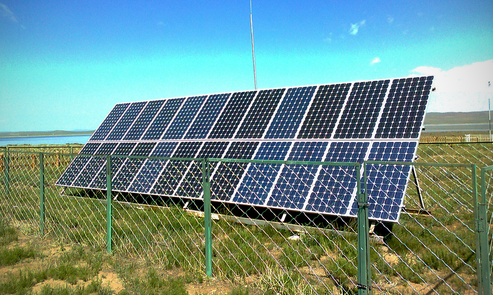
Solar Panels are turning out to be more well known today as a distinct option for conventional power era systems. By utilizing Solar Panels, we can outfit the Heat and Light energy gave by the sun and create power for anything from an icebox to a car. Have you ever seen Solar Panel secured rooftops or school zone signs with Solar Panels on and thought about how these Solar Panels work and what's going ahead "behind the boards?" "How do solar panels work?"


Lets take a gander at what Solar Panels are involved of and how solar panel innovation functions.

how do solar panels work - http://lifestyle-facts.blogspot.com


Solar Panel innovation is taking into account 2 sorts of sunlight based warmth accumulation: Solar power collectors and solar cells. Since for all intents and purposes of making solar cells are based on Solar panels, we'll concentrate on the Solar panel innovation. Solar cells, otherwise called photovoltaic cells, is the thing that makes up a photovoltaic board, or all the more regularly known as a Solar Panel. Try not to let the word photovoltaic threaten you. Lets break the word separately: photograph = light and voltaic = power (consider volt or voltage).

how do solar panels work - http://lifestyle-facts.blogspot.com


Basically it's speaking to the thought of changing over light into power. These photovoltaic cells are basically embody a semi-conductor, most generally silicon. I'm certain you have found out about silicon, and are really utilizing the innovation at this moment... in your Personal Computer, Silicon is utilized as a part of microchips, is is also utilized in every electronic semiconductor around the globe, is an exceptionally well known semi-conduit. At the point when light hits these silicon filled PV cells, the sunlight based vitality is consumed and a current is delivered inside the cell. By hanging together these Photovoltaic cells into a Solar panels, and putting contacts on the outside of this board, we have the capacity to take advantage of this electrical current.

how do solar panels work - http://lifestyle-facts.blogspot.com


Now that you know how Solar Panels work, what happens next?

When we have the Solar Panels wired and cooperating, they should be deliberately put in request to ensure they are presented to most extreme daylight. On account of utilizing solar panels at home, the rooftop would be the perfect place for the Solar Panels. It is essential to give careful consideration to the edge and situation of the boards to guarantee that Solar Panels work at their most elevated effectiveness. On the off chance that even one of the sun based cells is not completely presented to daylight, it can incredibly decrease the effectiveness of the whole board. It is likewise truly basic to change the edge of the boards through out the year so as to keep the solar panels presented to daylight amid the distinctive seasons. This may or may not be vital for you relying upon your individual design.

Right now we have created power, however the procedure is not complete yet. So as to have the capacity to utilize this vitality inside your home, we have to first change over the current from an Direct Current (DC) to an Alternate current (AC). To do this, we can utilize an inverter, which changes over this power into an AC current that family machines utilize. For example, an icebox or ventilation system have the capacity to utilize AC voltage. Another great step is to verify you store this vitality for times when either there is practically no daylight, for example, during the evening. This should be possible by putting away this power in batteries.


how do solar panels work - http://lifestyle-facts.blogspot.com

Deep cycling Batteries permit you to completely charge and revive using the current obtained from Solar Panels, keeping in mind the end goal to draw small amount of current over quite a long time. This is completely different from a car battery, where you require a bigger power boost for a brief time, i.e. when you ignite your car.

how do solar panels work - http://lifestyle-facts.blogspot.com


Next time you see Solar Panels at work, you'll see that it is a combination of Solar cells. On the off chance that you look carefully enough, you can see the individual Photovoltaic cells that make up each solar panels. Additionally, observe the boards position. Hope to perceive how others have expanded the boards presentation to the sun, by the stature, point, and situation of the board keeping in mind the end goal to permit the Solar Panels to work most productively.
Read More
  • Share This:  
  •  Facebook
  •  Twitter
  •  Google+
  •  Stumble
  •  Digg
Newer Posts Older Posts Home

Popular Posts

  • Simple +-400Watt Amplifier using TDA7294 or TDA7293 + Power Transistors 2SC5200 and 2SA1943
    This additional part can be added to the traditional chip amp made using TDA7294 or TDA7293 to gain extra power in output. The traditional c...
  • Audio Amplifier - 2N3055 MJ2955
    Here is A amplifier with 2n3055 transistors on its output for those of you that are looking at doing a bang for buck amplifier with all tho...
  • Stun Gun Circuit Diagram using 555 timer IC
    CAUTION: Before going to explain about this circuit, we are going to strictly suggest that DO NOT TRY TO IMPLEMENT IT PRACTICALLY AS IT PR...
  • A simple 12V battery charger schematic using LM317
    This is a simple 12Volt Battery Charger Circuit which can be made using less components. This circuit can be modified using the formulas giv...
  • Simple 3 Watt and 5 Watt LED Driver Circuit Using IC 338
    The IC LM338 as we probably are aware, is a profoundly adaptable gadget with regards to controlling voltages and current levels. In the pres...
  • Simple 150 Watt amplifier circuit using transistors
    This is the cheapest 150 Watt amplifier circuit you can make,I think.Based on two Darlington power transistors TIP 142 and TIP 147 ,this c...
  • Lead Acid Battery Charger Circuit
    To successfully charge a battery, it should be supplied with DC current and not AC. This circuit shows how you can use DC voltage to regulat...
  • How to easily repair Momentary Switches used in boats
    Momentary switches make generators and motors begin at the push of a catch. In any case, when they don't begin, consider the switch as o...
  • All the new content will be added to new blog - http://elektriktech.blogspot.com/
    Please visit the new blog http://elektriktech.blogspot.com/ for new content. Apologies for the inconvenience.     http://elektrikte...
  • Simple Car Audio Amplifier Circuit
    A straightforward low power car stereo amplifier circuit taking into account TDA 2003 is showed here. The circuit utilizes low cost, promptl...

Pages

  • Home

Blog Archive

  • ▼  2016 (2)
    • ▼  August (2)
      • All the new content will be added to new blog - ht...
      • How to easily repair Momentary Switches used in boats
  • ►  2015 (23)
    • ►  December (1)
    • ►  November (2)
    • ►  October (2)
    • ►  September (2)
    • ►  August (4)
    • ►  July (10)
    • ►  June (2)
  • ►  2013 (1)
    • ►  July (1)
  • ►  2011 (3)
    • ►  August (3)

Dear Visitor

Please visit the new blog http://elektriktech.blogspot.com/ for latest and updated content.

Contact Form

Name

Email *

Message *

About Me

dvbot
View my complete profile

UPDATE!

Please visit the new blog http://elektriktech.blogspot.com/ for all new contents.

Translate

Subscribe To

Posts
Atom
Posts
All Comments
Atom
All Comments

Copyright © Elektrik
Distributed By My Blogger Themes | Blogger Theme By NewBloggerThemes