
Inverter is a small circuit which will convert the direct current (DC) to alternating current (AC). The power of a battery is converted in to’ main voltages’ or AC power. This power can be used for electronic appliances like television, mobile phones, computer etc. the main function of the inverter is to convert DC to AC and step-up transformer is used to create main voltages from resulting AC.


In the block diagram battery supply is given to the MOSFET driver where it will convert DC to AC and the resulting AC is given to the step up transformer from the step up transformer we will the get the original voltage.
Main Components:
CD4047: CD4047 is a multi vibrator with very low power consumption designed by TEXAS INSTRUMENTS.it can operate in monostable multivibrator and also astable multivibrator.in the astable multivibrator mode it can operate in free running or gatable modes and also provides good astable frequency stability. It can generate 50% duty cycle which will create a pulse, which can be applied for inverter circuit. This is mainly used in frequency discriminators, timing circuits frequency divisions etc.
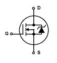
IRF540: IRF540 is a N-channel enhanced mode silicon gate field effect transistor (MOSFET).they are mainly used in switching regulators, switching converters relay drivers etc. the reason for using them in the INVERTER circuit is the because it is a high switching transistor , can work in very low gate drive power and have high input impedance.
IRF540 Symbol:
Simple 100W Inverter Circuit Diagram:
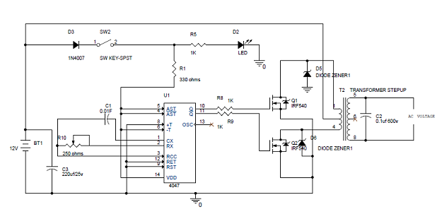
Explanation:
- In the circuit diagram we can observe that 12V battery is connecter to the diode LED and also connected to the pin8 of the IC 4047 which is VCC or power supply pin and also to pin 4 and 5 which are astable and complement astable of the IC. Diode in the circuit will help not give any reverse current, LED will work as a indicator to the battery is working or not.
- IC CD4047 will work in the astable multivibrator mode. To work it in astable multivibrator mode we need an external capacitor which should be connected between the pin1 and pin3. Pin2 is connected by the resistor and a variable resistor to change the change the output frequency of the IC. Remaining pins are grounded .The pins 10 and 11 are connected to the gate of the mosfets IRF540. The pin 10 and 11 are Q and ~Q from these pins the output frequencies is generated with 50% duty cycle.
- The output frequency is connected to the mosfets through resistor which will help to prevent to the loading of the mosfets. The main AC current is generated by the two mosfets which will act as a two electronic switches. The battery current is made to flow upper half or positive half of the primary coil of transformer through Q1 this is done when the pin 10 becomes high and lower half or negative half is done by opposite current flow through the primary coil of transformer, this is done when pin 11 is high. By switching the two mosfets current is generated.
- This AC is given to the step up transformer of the secondary coil from this coil only we will get the increased AC voltage , this AC voltage is so high; from step up transformer we will get the max voltage. Zenor diode will help avoid the reverse current.
NOTE: The generated AC is not equal to the normal AC mains or house hold current. You cannot use this voltage for pure electric appliances like heater, electric cooker etc. Because of the fast switching of mosfets heat is dissipated which will effect the efficiency, use heat sink to remove this problem. The transformer can be bought through transformer manufacturer in your city or town.


 Posts
Posts


Good job ! 7 months and no comments !! Did you try this circuit out ?
ReplyDeleteI have but not alone, a classmate and I did and it's currently functional at his house.
ReplyDelete